
Lesson 2 – T: Transform Your Learning: How Do Electrical Circuits Work Safely?
T: Transform Your Learning
Show What You Can Do and Connect It Forward
Resistance Changes Current
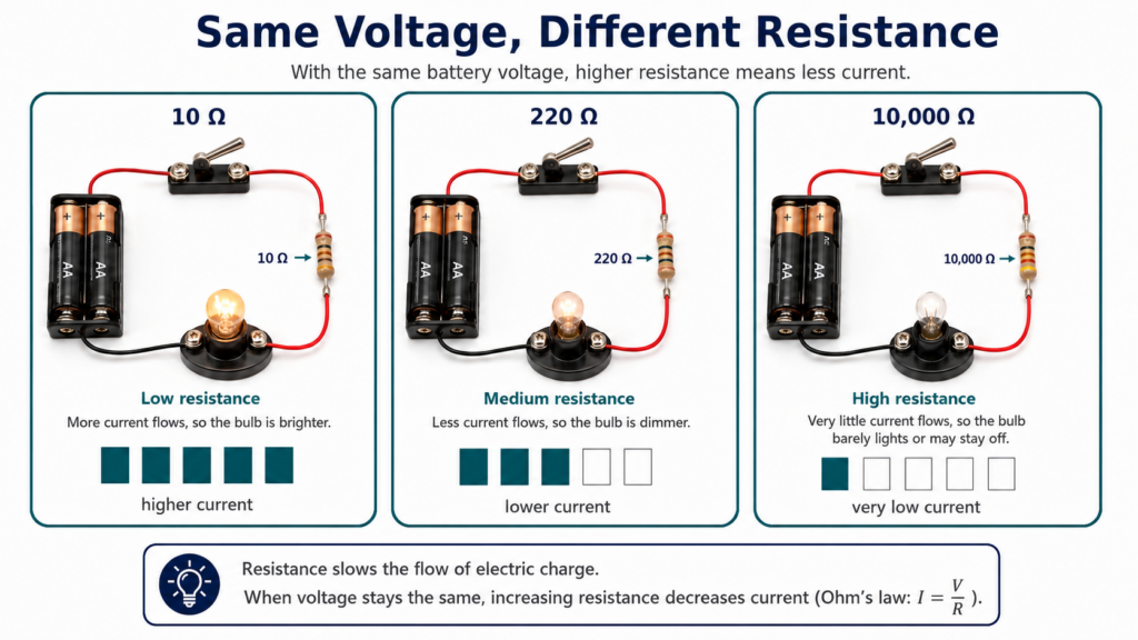
So far, you have focused on whether current can flow. Engineers also need to control how much current flows. Resistance is opposition to current. When resistance increases, less current flows through the circuit. When resistance decreases, more current can flow.
One way to think about resistance is a garden hose. If the hose is wide open, more water can flow. If the hose is pinched, less water can flow. Resistance is not exactly the same as pinching a hose, but the analogy helps show that the path can make flow easier or harder.
Resistance Investigation
In this investigation, the voltage stays the same at 3 V. You will change only the resistance. Before each test, predict how bright the bulb will be. Then observe the bulb and record what happens.
|
Resistance |
Predicted Brightness |
Observed Brightness |
|---|---|---|
|
10 Ω |
|
|
|
220 Ω |
|
|
|
10,000 Ω |
|
|
PhET Simulation
Optional: If you’d like, open the PhET simulation and create a closed circuit with a battery, wires, resistor, and bulb. Then adjust the resistor value to the 10 Ω, 220 Ω, and 10,000 Ω, and record if the observed brightness matched your prediction or not.
Explain With Evidence
How did resistance affect current and bulb brightness? Use numbers from the table and observations from the simulation.
Connect to Solar Mini-Grids
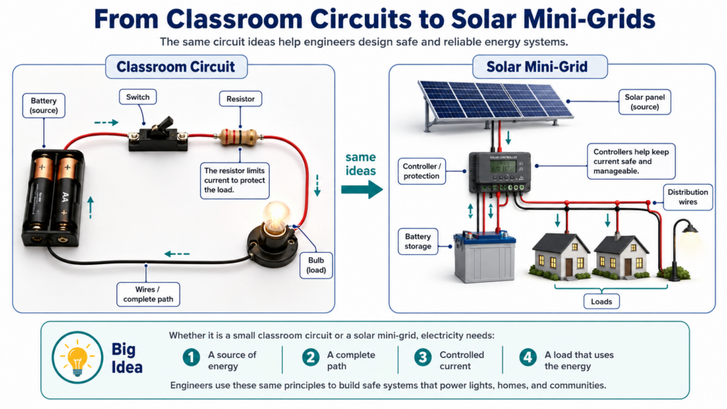
Classroom circuits are small models, but the same ideas help engineers design larger systems. A solar mini-grid also needs a complete and controlled path. Solar panels or batteries provide electrical energy. Conductors carry current. Loads use the energy. Switches and other controls help manage when and where current flows.
|
Classroom Circuit |
Solar Mini-Grid Connection |
|---|---|
|
Battery |
Solar panel or battery storage |
|
Wires |
Conductors that carry current |
|
Bulb |
Homes, lights, or devices using energy |
|
Switch |
Device or system control |
|
Resistor or load |
Components that affect or use current |
Engineering Insight
A safe and effective electrical system needs both a complete path and a controlled path.
Check Your Understanding
- What is the difference between an open circuit and a closed circuit?
- What is a short circuit?
- Which safety rule do you think is most important, and why?
- Describe one thing you learned about resistance.
Closure: Connecting Lesson 2 to Lesson 3
In Lesson 2, you learned that current needs a complete path to move and a controlled path to move safely. You compared closed circuits, open circuits, short circuits, switches, and resistance. You also used Ohm’s Law to see how resistance affects current.
In Lesson 3, you will build on these ideas by measuring voltage and current in a real circuit. You will use those measurements to calculate power and energy. Instead of only asking, “Does the circuit work safely?” you will begin asking, “How much power and energy is this circuit using?”