
Lesson 3 – O: Orient Your Learning: Measuring Power & Energy
O: Orient Your Learning
Current, Multimeters, and Breadboards
Direct Current and Alternating Current
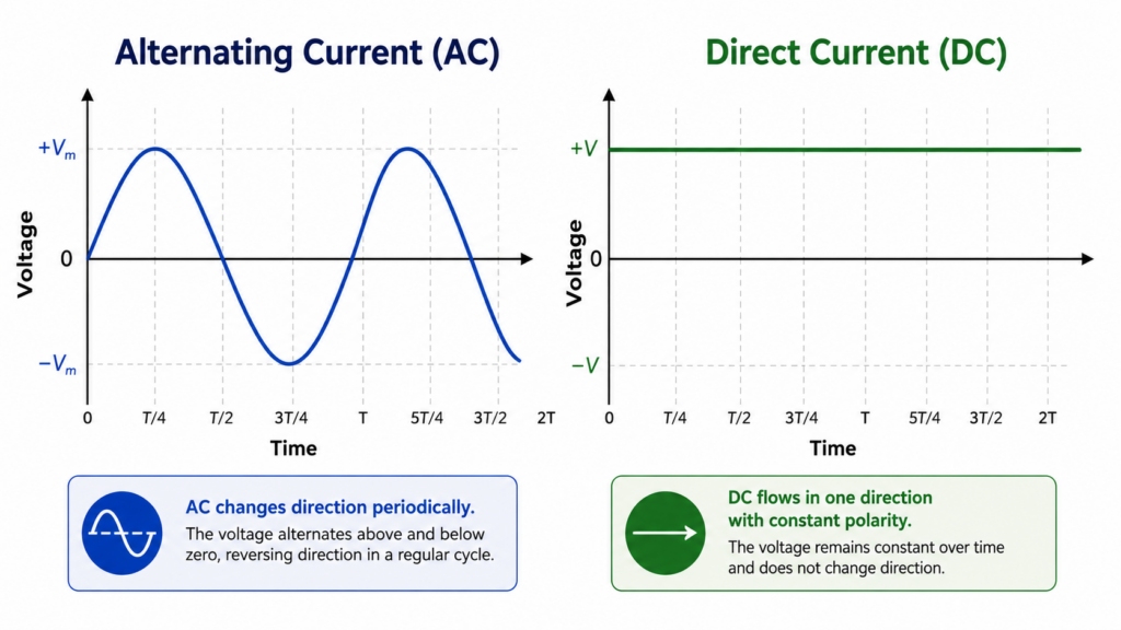
Electric current is the movement of electric charge. There are two major types of current: direct current and alternating current. The difference is the direction the charge moves.
Direct current, or DC, flows in one direction. Batteries provide DC electricity because charge leaves one side of the battery, moves through the circuit, and returns to the other side. Solar panels also produce DC electricity.
Alternating current, or AC, changes direction periodically. In many homes and buildings, outlets provide AC electricity. The voltage rises, falls, reverses direction, and repeats this cycle many times per second.
|
Type of Current |
How It Behaves |
Common Examples |
|---|---|---|
|
DC |
Charge flows in one direction. |
Batteries, solar panels, simple classroom circuits |
|
AC |
Charge changes direction periodically. |
Wall outlets and many household electrical systems |
|
IN THIS LESSON |
|---|
|
You will work with a DC circuit powered by batteries. The ideas of voltage, current, power, and energy apply to both DC and AC circuits, but classroom battery circuits are safer and easier to measure. |
How a Multimeter Helps Engineers Measure Circuits
A multimeter is a handy tool that can measure several things in an electrical circuit. It can measure voltage, or the electrical push; current, or the flow of electricity; and resistance, or how much a part slows down the flow. Without a multimeter, you would need separate tools: a voltmeter to measure voltage, an ammeter to measure current, and an ohmmeter to measure resistance. Using one multimeter makes it easier for students and engineers to test circuits and understand how electricity is working.
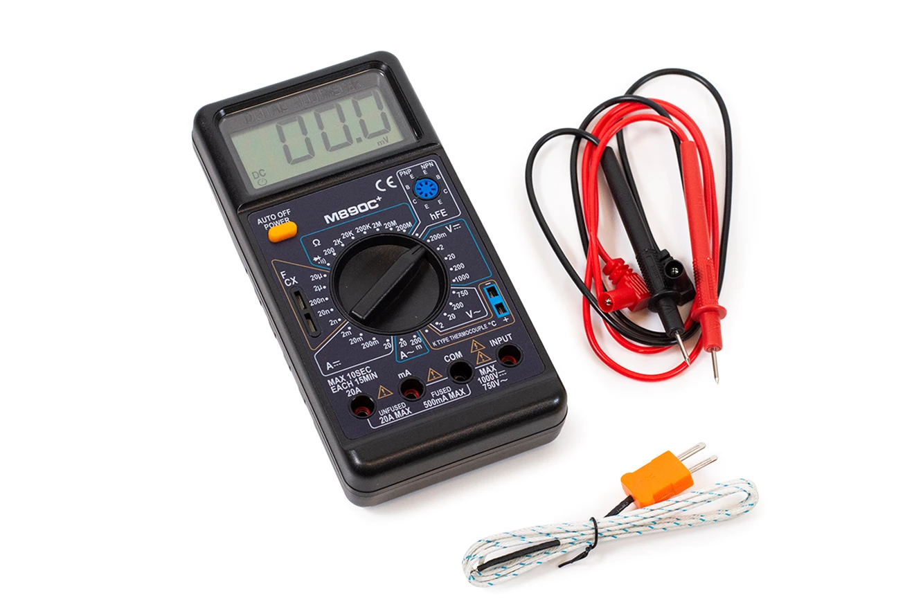
To measure anything, we need a way to point to it, and for that, we need “probes” which are small needle-like red and black leads that can be plugged into the multimeter.
There are connections on the multimeter where the probes are plugged in. The first is the black one labeled COM. The “COM” stands for “Common” and most typically represents “ground” or the negative (“- “) connection.
The positive terminal is a bit more complicated. Depending on what you want to measure and the quantity of resistance, you will plug your positive probe into the corresponding terminal.
- For voltage, resistance, or continuity measurements, connect the red lead to the terminal labeled VΩHz (or VΩ), and connect the black lead to COM.
- To measure small current—within the limit printed beside the mA terminal—connect the red lead to the mA terminal. This is common for many low-voltage classroom circuits, such as battery–resistor–LED circuits.
- To measure larger current, or when the expected current is unknown, begin with the red lead in the 10A terminal and select the matching current range. If the reading is safely below the mA-terminal limit, power off the circuit and move the red lead to mA for a more precise reading.
- When measuring current, always open the circuit and place the multimeter in series with the current path—never directly across a battery or power supply.
Multimeter Quick Guide
Use this guide to help you determine how to connect your leads and where the probes go based on what you are measuring.
Always connect the black lead to COM.
Move the red lead only when you change what you are measuring.
|
What Are You Measuring? |
Red Lead Terminal |
Meter Setting |
Where Do the Probes Go? |
Key Reminder |
|---|---|---|---|---|
|
Voltage |
Voltage input—often labeled V, VΩ, or VΩHz. Some meters use INPUT; check the manual. |
DC V for batteries and solar cells. Use AC V only for an instructor-approved AC source. |
Touch the probes across the battery, solar cell, or component. |
Voltage is measured across a component. |
|
Resistance |
Resistance input—usually shared with the voltage input and marked Ω. Check the manual. |
Ω |
Touch probes to the two ends of the resistor or component. |
Power off the circuit first. |
|
Continuity |
Input assigned to continuity—usually shared with voltage/resistance. Check the manual. |
Continuity setting—often marked with a sound-wave symbol. Confirm the symbol in the manual. |
Touch the probes to the two points you want to check for a connected path. |
Power off the circuit first. A beep usually means the path is connected. |
|
Small current |
Input assigned to mA/µA—may be separate or shared with other functions. Check the manual. |
DC mA or DC A, with the range selected according to the manual and expected current. |
Open the circuit at the measurement point and insert the meter in series, so current flows through the meter. |
Use only when the expected current is below the input’s specified limit. |
|
Larger or unknown current |
High-current input—may be labeled A, 10A, or 20A. Use only if approved for the task. |
DC A, with the range selected according to the manual and expected current. |
Open the circuit at the measurement point and insert the meter in series. |
Instructor approval required. Follow the input’s current and time limits. |
Black lead: COM. Match the red-lead input and dial setting to the measurement. Never measure voltage with the red lead in a current input. Follow your exact meter’s instructions and limits.
Check Your Understanding
How is measuring voltage different from measuring current?
How a Breadboard Helps You Build a Circuit
A breadboard is a tool for building temporary circuits. It is essentially is a map of hidden connections that you use to build a complete, controlled path from a power source, through a component, and back to the source. It lets you connect components without soldering.
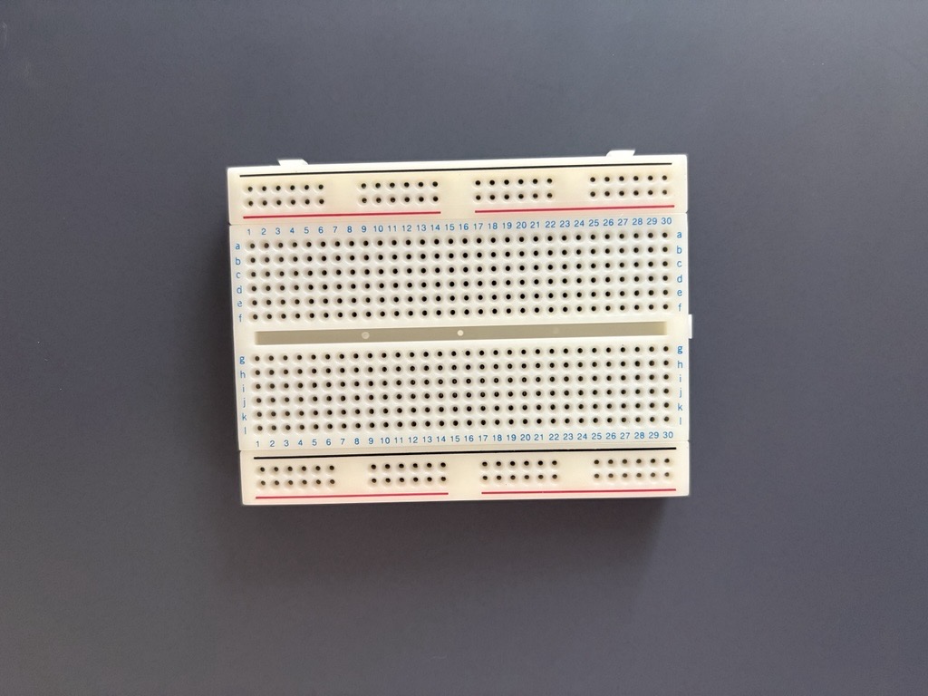
Use the chart below with the image above to locate the parts of a breadboard.
Breadboard Parts and Connections
|
Breadboard Part |
What It Looks Like |
What is Connected Underneath |
Main Job |
Important Reminder |
|---|---|---|---|---|
|
Terminal strips |
The large center grid of holes, usually labeled A–J and numbered by rows |
Each group of five holes on one side of the center gap is connected: A–E or F–J in the same numbered row. |
Connect component leads and jumper wires to make circuit nodes. |
Connections go across five holes, not up and down the board. |
|
Five-hole group |
Example: A10, B10, C10, D10, and E10 |
All five holes share one electrical connection. |
Lets several leads meet at one point in a circuit. |
Do not put both legs of a two-leg component into the same group; it bypasses the component. |
|
Center gap (trench) |
Long empty channel down the middle |
No electrical connection crosses the gap. |
Gives integrated circuits space to straddle the middle safely. |
A–E are not connected to F–J, even when the row number matches. |
|
Power rails (bus strips) |
Long rows near the outer edges, often marked red + and blue/black – |
Holes usually connect lengthwise along one rail. |
Distribute positive supply and ground around the board. |
The + and – rails are separate from each other. |
|
Split power rail (Note: only on some breadboards) |
A visible break in the red or blue marking, often near the middle |
The two portions are not connected internally. |
Allows separate supplies or circuit sections. |
Use a jumper wire to bridge the break only if you want one continuous rail. |
|
Hole / tie point |
One plug-in hole |
A metal spring clip connects it to its group or rail. |
Holds a solid-core wire or component lead. |
A hole is a connection point—not a direction of current flow. |
|
Row numbers and letters |
Numbers along the side; letters across the middle |
Labels only |
Help identify exact locations in directions and troubleshooting. |
“E7” means column E, row 7. |
When using a breadboard to build a circuit, the goal is to create one complete path for current to travel. If there is a break in the path, current will not flow. Let’s say you are trying to light an LED light bulb. If you do not have a complete path for the current to flow, the LED will not light. If the circuit accidentally gives current a direct path around the resistor or LED, it can create a short circuit.
It is also important to check polarity before powering on. Checking polarity means making sure the positive (+) and negative (−) sides of a circuit are connected the right way before turning on the power. Some parts, such as LEDs, only work when electricity flows in one direction. To check, look for the + and − labels on the battery holder and component, or use a multimeter while the circuit is powered off. For an LED, the longer leg is usually positive, and the shorter leg or flat side is negative.
Checking polarity is important because connecting parts backward can keep the circuit from working and may damage some components.
Pause and Think
Why is it important to understand the breadboard before powering the circuit?
Safety Reminder
- Build with the power off.
- Check LED polarity.
- Make sure the resistor is in the path.
- Avoid short circuits.
- Wait for instructor approval before applying power.
It is important to maintain safe practices when you are building circuits. Before You Power On: PATH Check
- Power off: Do not add, remove, or move wires while the battery is connected.
- Analyze the rails: Is + separate from −? Is there any wire directly connecting them?
- Trace the path: Can you trace one intended route: + → resistor → LED/load → −?
- Have a check: Ask your partner and instructor to inspect the circuit before connecting power.
Common Accidental Short Mistakes
|
What Someone Might Do |
Why It Is a Problem |
Safer Correction |
|---|---|---|
|
Put a jumper directly from the + rail to the − rail. |
It creates a direct battery shortcut. |
Remove it; ensure every +-to-− route includes the intended load/resistor. |
|
Put both legs of a component in the same connected row. |
The component may be bypassed because both legs are at the same electrical point. |
Move one leg to a different row or to the other side of the center gap, as shown in the diagram. |
|
Connect the battery before building is complete. |
A misplaced wire can energize an unintended path. |
Build first; connect the battery last. |
|
Change wires while power is connected. |
A loose lead can briefly touch the wrong row or rail. |
Disconnect the battery before every modification. |
|
Run an LED without its required series resistor. |
The LED may receive too much current and be damaged. |
Verify the resistor is in series before power-on. |
|
Assume colored rails are always connected exactly as expected. |
Rails may be split or arranged differently across boards. |
Use the board diagram; verify the specific board if uncertain. |
|
Treat an LED like a resistor. |
LEDs are polarized and must be oriented correctly. |
Check the LED’s long leg/anode and short leg/cathode before power-on. |
Think About It
Calculate Power and Energy using the information in the table. How do you think the values might be different based on the resistance?