
Instructor Guide Sample Lesson: Measuring Power & Energy Sample Lesson
|
BRIDGE FROM PREVIOUS LESSON |
|---|
|
In the previous lesson, learners practiced safety routines and basic circuit concepts. In Lesson 3, learners use a multimeter to measure voltage and current, then use those measurements to calculate power and energy, building from complete circuit language into measurement. |
|
Lesson Overview |
Essential Questions |
Learning Objectives |
|---|---|---|
|
Learners assemble a simple LED circuit on a breadboard, measure voltage and current safely, calculate power with P = V × I, and calculate energy over time using watt-hours. |
|
|
|
ENDURING UNDERSTANDING |
|---|
|
Understanding and measuring electrical circuits enables engineers to calculate power and energy accurately, supporting informed decisions and the design of reliable, sustainable energy solutions for communities without access to power. |
National Standards Alignment
|
Standard |
Connection to This Lesson |
|---|---|
|
HS-PS3-3 Energy |
Learners measure voltage and current, calculate power and energy, and use those measurements to explain how an electrical device converts and uses energy within an engineered circuit. |
|
MS-ETS1-3 Engineering Design |
Learners analyze data from circuit tests before and after a design modification, then compare how the modification changes current, power, and usefulness for an energy-system design. |
|
SEP |
How Learners Use the Practice |
|---|---|
|
Planning and Carrying Out Investigations |
Learners assemble a circuit, measure voltage/current, and collect data using a multimeter. |
|
Using Mathematics and Computational Thinking |
Learners calculate power and energy from measured values. |
|
Analyzing and Interpreting Data |
Learners compare measurements before and after changing one circuit variable. |
|
Standard |
Connection to This Lesson |
|---|---|
|
CCSS.Math.Content.HSA-CED.A.4 |
Learners use and rearrange formulas such as P = V × I and E = P × t to highlight the quantity of interest and interpret circuit measurements. |
|
CCSS.Math.Content.HSN-Q.A.1 |
Learners identify and consistently use volts, amperes, watts, hours, and watt-hours in their measurement table and calculations. If current is recorded in milliamperes, they convert it before using a formula expecting amperes. |
|
CCSS.ELA-Literacy.RST.6-8.3 |
Learners follow a multistep technical procedure to assemble a circuit, take measurements, and record values accurately. |
|
CCSS.ELA-Literacy.RST.9-10.3 |
Learners follow written assembly and measurement instructions that explicitly address relevant special cases—for example, changes in meter setup for voltage versus current or differences between breadboard layouts. |
|
Source |
URL |
|---|---|
|
Next Generation Science Standards (NGSS) |
|
|
Common Core State Standards (CCSS) |
Materials & Setup
|
Item |
Format |
Notes for Instructor |
|---|---|---|
|
3–4 Chargers, Adapters |
Virtual option: projected device labels where learners can see the voltage and current ratings. |
Suggested examples: phone charger, laptop charger, LED strip adapter, or small USB fan. |
|
Breadboard |
Virtual Option: https://phet.colorado.edu/en/simulations/circuit-construction-kit-dc |
Used as the platform for circuit assembly. |
|
Two AA batteries and battery holder or a 9 V battery and battery holder |
Virtual Option: https://phet.colorado.edu/en/simulations/circuit-construction-kit-dc |
Provides 3 V DC supply. |
|
LED |
Materials kit |
Check polarity before powering circuit. |
|
Jumper wires |
Materials kit |
Use to complete the circuit paths. |
|
Resistors |
Materials kit |
If using a 9V battery: 470 Ω, 1k Ω, 2.2k Ω |
|
Multimeter |
Materials kit |
Set to DC volts for voltage and inserted in series for current. |
|
Phone charger or laptop adapter |
Instructor demo item |
Used for the hook. |
Key Vocabulary and Concepts
|
Term |
Definition |
|---|---|
|
Energy |
Power used over time. Measured in watt-hours (Wh). 1,000 Wh = 1 kilowatt-hour (kWh). It is calculated using the formula E = P x t. |
|
Direct Current (DC) |
Charge flows in one direction; batteries and solar panels provide DC electricity, and classroom battery circuits are examples of DC circuits. |
|
Alternating Current (AC) |
Charge changes direction periodically; wall outlets and many household electrical systems provide AC electricity, where voltage rises, falls, reverses direction, and repeats. |
|
Multimeter |
An engineering tool used to measure different electrical quantities in a circuit, such as voltage, current, and resistance; in this lesson, it is used to measure voltage and current. |
|
Breadboard |
A tool for building temporary circuits without soldering; inside the breadboard, groups of holes are connected by metal strips that organize circuit connections into rows and power rails. |
|
LED |
A light-emitting diode used in the circuit; it uses electrical energy to produce light and has polarity, so it must face the correct direction to light. |
|
Resistor |
A component that limits current and protects the LED in the circuit; changing the resistor value changes current and therefore affects power and energy use. |
|
INSTRUCTOR PREPARATION |
|---|
|
V: Voyage Into Volt
Anticipated timing: 5 minutes
Purpose: Activate curiosity by connecting power measurement to everyday devices.
Power Detective Prediction Sort — Setup Before Lesson
|
PREPARE THE ROOM |
|---|
|
Place 3-4 chargers, adapters, or projected device labels where learners can see the voltage and current ratings.
Suggested examples: phone charger, laptop charger, LED strip adapter, or small USB fan. |
|
DISPLAY |
|---|
|
Collaborative challenge: Which device uses the most power? Rank the devices from lowest to highest power. |
|
PROPOSE THIS |
|---|
|
“Your group is going to act like a team of electrical engineers. Look at the information printed on each charger or adapter and make a prediction: which one uses the most power? Be ready to explain what evidence you used.” |
|
DISCUSSION QUESTIONS |
|---|
|
Power Detective Prediction Sort — Procedure
- Note: If learners completed the Learner Lesson, they will have sorted an example group of labels from that content on their Learner Guide already. You will now have them do the same with a second set of labels.
|
PURPOSE |
|---|
|
Learners work collaboratively to discover that voltage alone does not determine how much power a device uses. They begin to see that power depends on both voltage and current. |
|
PROCEDURE |
|---|
|
|
KEY TAKEAWAY |
|---|
|
Power depends on both voltage and current. Measuring only one value does not tell the whole energy story. |
|
TRANSITION |
|---|
|
Today we will become power detectives in our own circuits. Instead of reading the numbers from a charger label, we will measure voltage and current ourselves, then use those measurements to calculate power and energy. |
O: Orient the Learning
Anticipated timing: 15 minutes
Purpose: Review AC/DC concepts, multimeter use, formulas, units, and breadboard structure before hands-on measurement.
Concepts Review — Procedure
|
INSTRUCTOR NOTE |
|---|
|
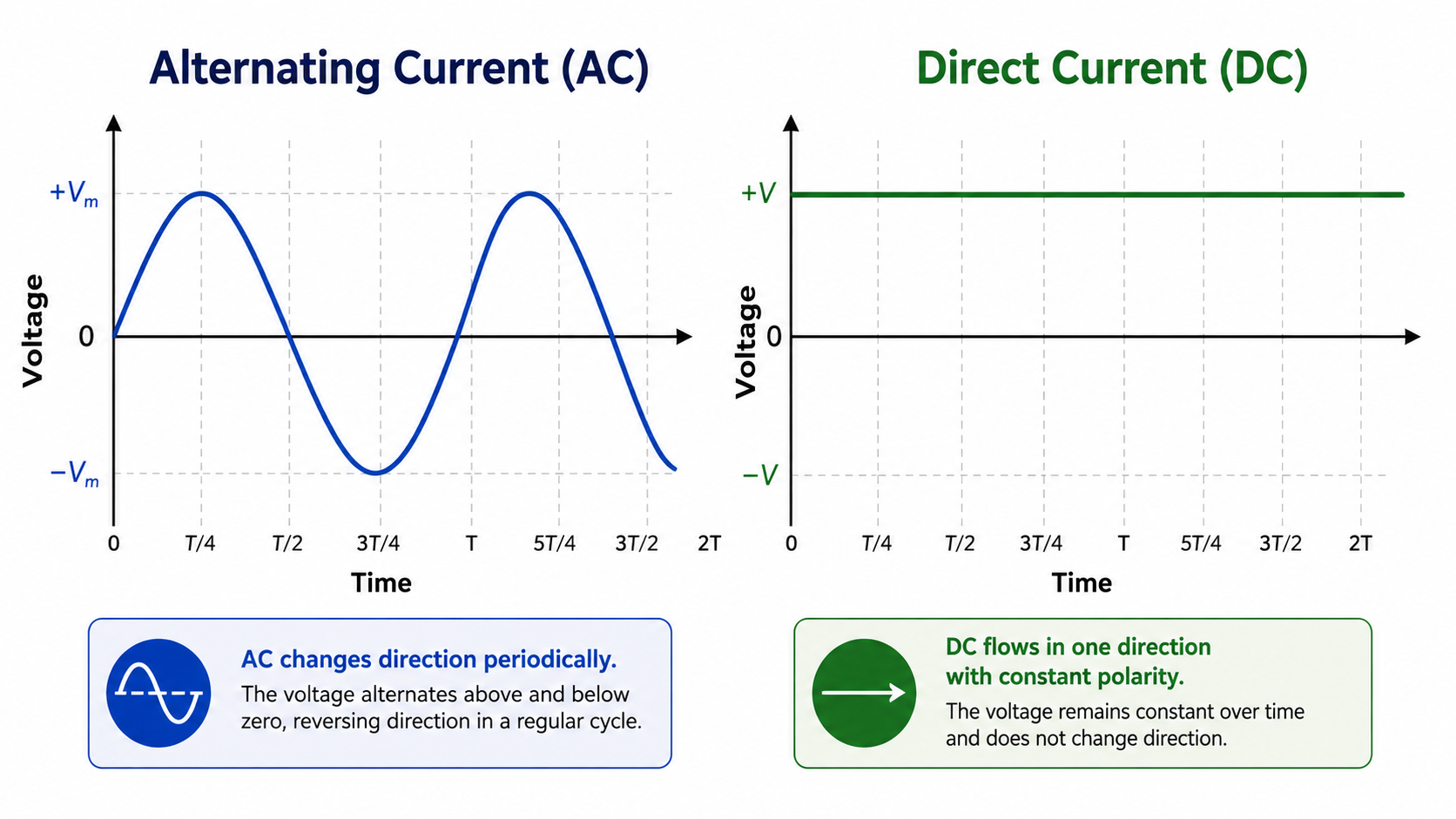
Before learners deep dive into measuring circuits, orient them to the difference between direct current and alternating current. |
Alternating current, or AC, changes direction periodically. Voltage and current move from positive to zero to negative, then back again, forming a sine wave.
Direct current, or DC, is a constant flow of electric charge in one direction only. In a DC circuit, voltage remains constant and current flows in the same direction.
|
INSTRUCTION POINT |
|---|
|
Solar panels produce DC current, while most home appliances use AC current. In this lesson, learners explore a simple DC circuit, and the terms voltage, current, power, and energy apply to both DC and AC circuits. |
|
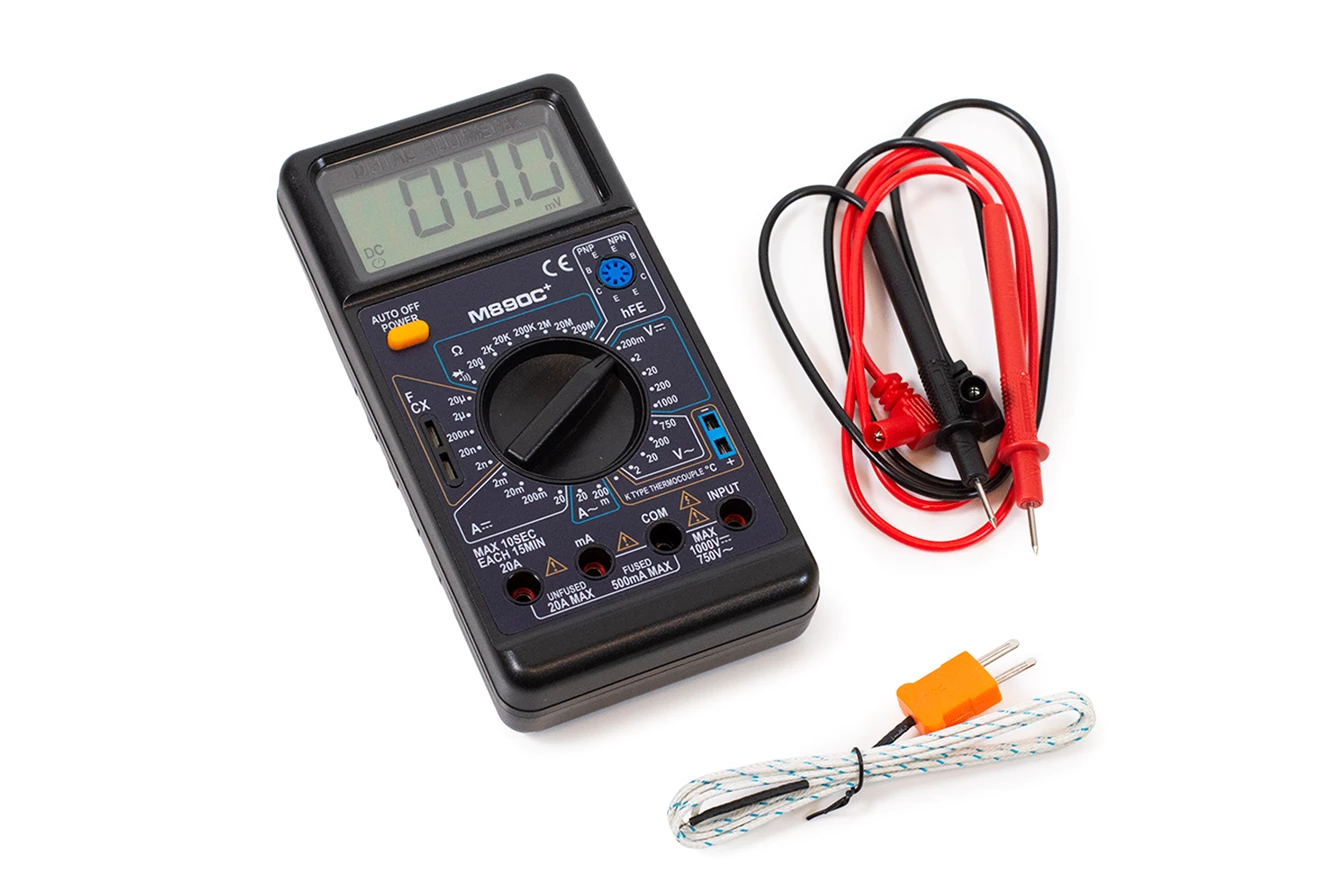
INTRODUCING THE MULTIMETER |
|---|
|
Introduce learners and familiarize them with the multimeter. |
|
PROPOSE THIS |
|---|
|
“A multimeter is an engineering tool used to measure different electrical quantities in a circuit. In this lesson, learners will use it to measure voltage, which tells us about the electrical push across a component, and current, which tells us how much electric charge is flowing through the circuit. The multimeter has different settings because it can measure different things, so we must always check the dial before measuring. For today’s investigation, we want to remember the following: voltage is measured across a component, while current is measured in series by placing the meter into the circuit path. Careful measurement helps engineers move from guessing to evidence-based decisions about power and energy. “ |
Multimeter Quick Guide
|
What Are You Measuring? |
Red Lead Terminal |
Meter Setting |
Where Do the Probes Go? |
Key Reminder |
|---|---|---|---|---|
|
Voltage |
Voltage input—often labeled V, VΩ, or VΩHz. Some meters use INPUT; check the manual. |
DC V for batteries and solar cells. Use AC V only for an instructor-approved AC source. |
Touch the probes across the battery, solar cell, or component. |
Voltage is measured across a component. |
|
Resistance |
Resistance input—usually shared with the voltage input and marked Ω. Check the manual. |
Ω |
Touch probes to the two ends of the resistor or component. |
Power off the circuit first. |
|
Continuity |
Input assigned to continuity—usually shared with voltage/resistance. Check the manual. |
Continuity setting—often marked with a sound-wave symbol. Confirm the symbol in the manual. |
Touch the probes to the two points you want to check for a connected path. |
Power off the circuit first. A beep usually means the path is connected. |
|
Small current |
Input assigned to mA/µA—may be separate or shared with other functions. Check the manual. |
DC mA or DC A, with the range selected according to the manual and expected current. |
Open the circuit at the measurement point and insert the meter in series, so current flows through the meter. |
Use only when the expected current is below the input’s specified limit. |
|
Larger or unknown current |
High-current input—may be labeled A, 10A, or 20A. Use only if approved for the task. |
DC A, with the range selected according to the manual and expected current. |
Open the circuit at the measurement point and insert the meter in series. |
Instructor approval required. Follow the input’s current and time limits. |
Black lead: COM. Match the red-lead input and dial setting to the measurement. Never measure voltage with the red lead in a current input. Follow your exact meter’s instructions and limits.
|
Term |
Symbol |
Units |
|---|---|---|
|
Voltage |
V |
Volts |
|
Current |
I |
Amperes or amps |
|
Power |
P |
Watts |
|
Energy |
E |
Watt-hours |
|
INSTRUCTION POINT |
|---|
|
Power = Voltage × Current, so P = V × I. Energy = Power × time, so E = P × t. |
Using the Breadboard
|
INSTRUCTOR NOTE |
|---|
|
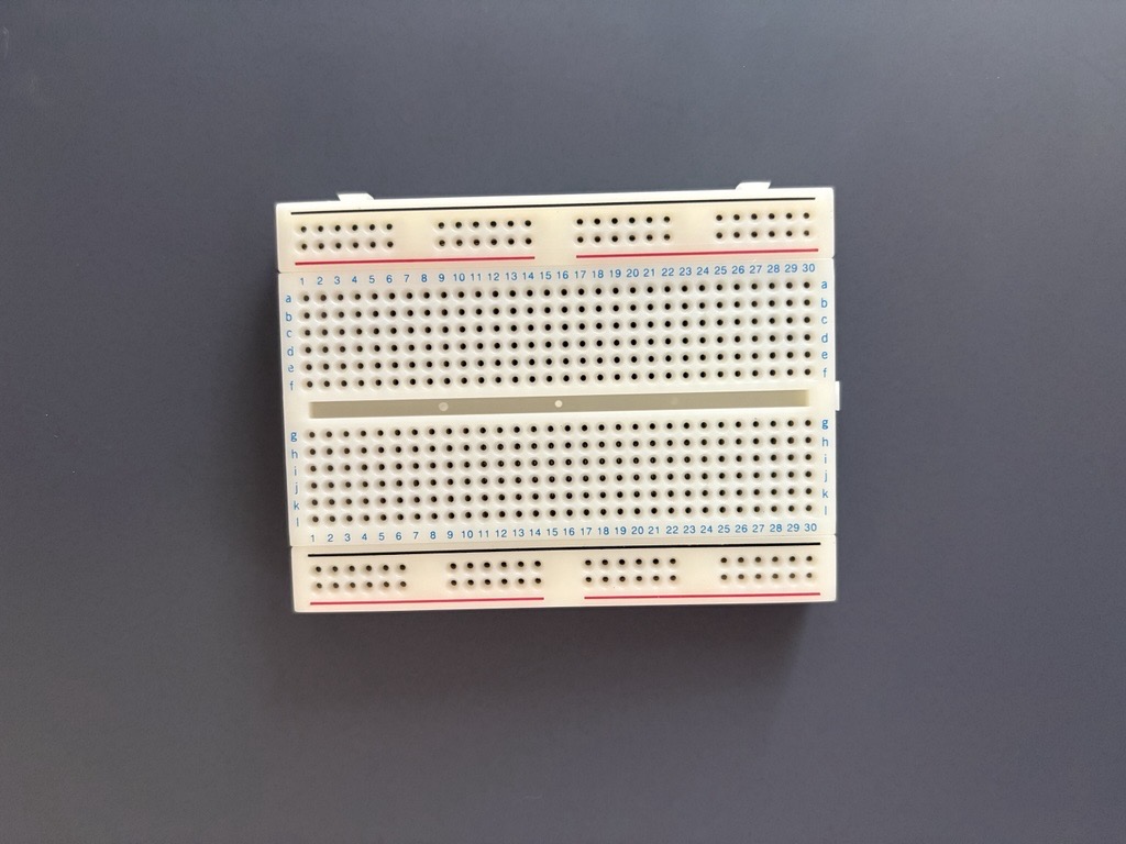
Review how the breadboard organizes connections before learners begin assembly. |
Breadboard Parts and Connections
|
Breadboard Part |
What It Looks Like |
What is Connected Underneath |
Main Job |
Important Reminder |
|---|---|---|---|---|
|
Terminal strips |
The large center grid of holes, usually labeled A–J and numbered by rows |
Each group of five holes on one side of the center gap is connected: A–E or F–J in the same numbered row. |
Connect component leads and jumper wires to make circuit nodes. |
Connections go across five holes, not up and down the board. |
|
Five-hole group |
Example: A10, B10, C10, D10, and E10 |
All five holes share one electrical connection. |
Lets several leads meet at one point in a circuit. |
Do not put both legs of a two-leg component into the same group; it bypasses the component. |
|
Center gap (trench) |
Long empty channel down the middle |
No electrical connection crosses the gap. |
Gives integrated circuits space to straddle the middle safely. |
A–E are not connected to F–J, even when the row number matches. |
|
Power rails (bus strips) |
Long rows near the outer edges, often marked red + and blue/black – |
Holes usually connect lengthwise along one rail. |
Distribute positive supply and ground around the board. |
The + and – rails are separate from each other. |
|
Split power rail (Note: only on some breadboards) |
A visible break in the red or blue marking, often near the middle |
The two portions are not connected internally. |
Allows separate supplies or circuit sections. |
Use a jumper wire to bridge the break only if you want one continuous rail. |
|
Hole / tie point |
One plug-in hole |
A metal spring clip connects it to its group or rail. |
Holds a solid-core wire or component lead. |
A hole is a connection point—not a direction of current flow. |
|
Row numbers and letters |
Numbers along the side; letters across the middle |
Labels only |
Help identify exact locations in directions and troubleshooting. |
“E7” means column E, row 7. |
|
DISCUSSION QUESTIONS |
|---|
|
|
SAFETY FIRST — REMINDER |
|---|
|
A pre-power safety routine P — Power off: The battery pack is unplugged or switched off while wiring. A — Analyze the rails: Identify which rail is + and which is −. Check that no jumper directly joins them. T — Trace the path: Use a finger or pencil to trace from battery + through the resistor and LED/load, back to battery −. H — Have a partner check: A partner independently traces the same path, then the instructor approves it before power-on.
|
L: Launch the Learning
Anticipated timing: 25 minutes
Purpose: Guide pairs through safe circuit assembly, voltage measurement, current measurement, and power/energy calculation.
Guided Assembly — Setup Before Lesson
|
PREPARE THE ROOM |
|---|
|
Divide learners into pairs. Give each pair a material bag and make sure the projected wiring diagram is visible. |
|
DISPLAY |
||||||||||||||||
|---|---|---|---|---|---|---|---|---|---|---|---|---|---|---|---|---|
|
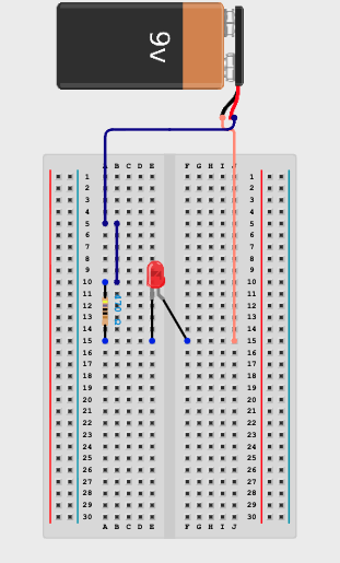
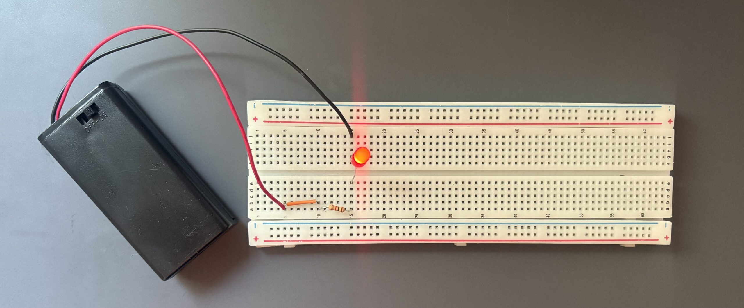
Circuit path: Battery → resistor → LED → back to battery.
 Circuit Specifications
|
Guided Assembly — Procedure
|
PROCEDURE |
|---|
|
Step 1: Learners assemble the circuit. The instructor circulates and checks each circuit before learners power it on. Basic LED Circuit and Current MeasurementUse a battery – We recommend either a 3 V battery pack (two AA cells), or a 9V battery, one standard LED, and one resistor (start with the 470 ohm resistor no matter which battery type you will use). The resistor is required: it limits current and helps protect the LED.
Assumption: Your breadboard has columns labeled A–J and numbered rows. In each numbered row, holes A–E are electrically connected together, and F–J are connected together; the center gap separates the two sides.
Build the LED CircuitWiring Diagram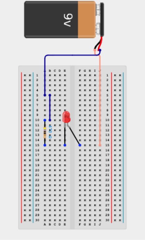
Battery + –> A5/B5 –> jumper –> B10/A10 –> resistor –> A15/E15 –> LED –> F15/J15 –> Battery – |
|
CIRCULATE AND OBSERVE |
|---|
|
Check that the LED polarity is correct, the resistor is in the path, the circuit is complete, and there are no direct short circuits before power is applied. |
|
PROCEDURE |
|---|
|
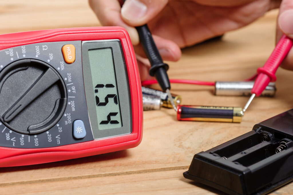
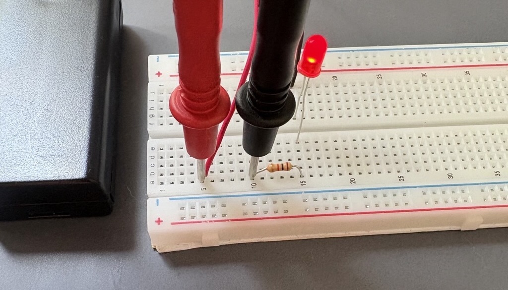
Step 2: Measure voltage. Set the multimeter to DC volts. Measure across the resistor by placing probes on both sides of the load. Record the measurement in Data Table 1. |
|
PROCEDURE |
|---|
|
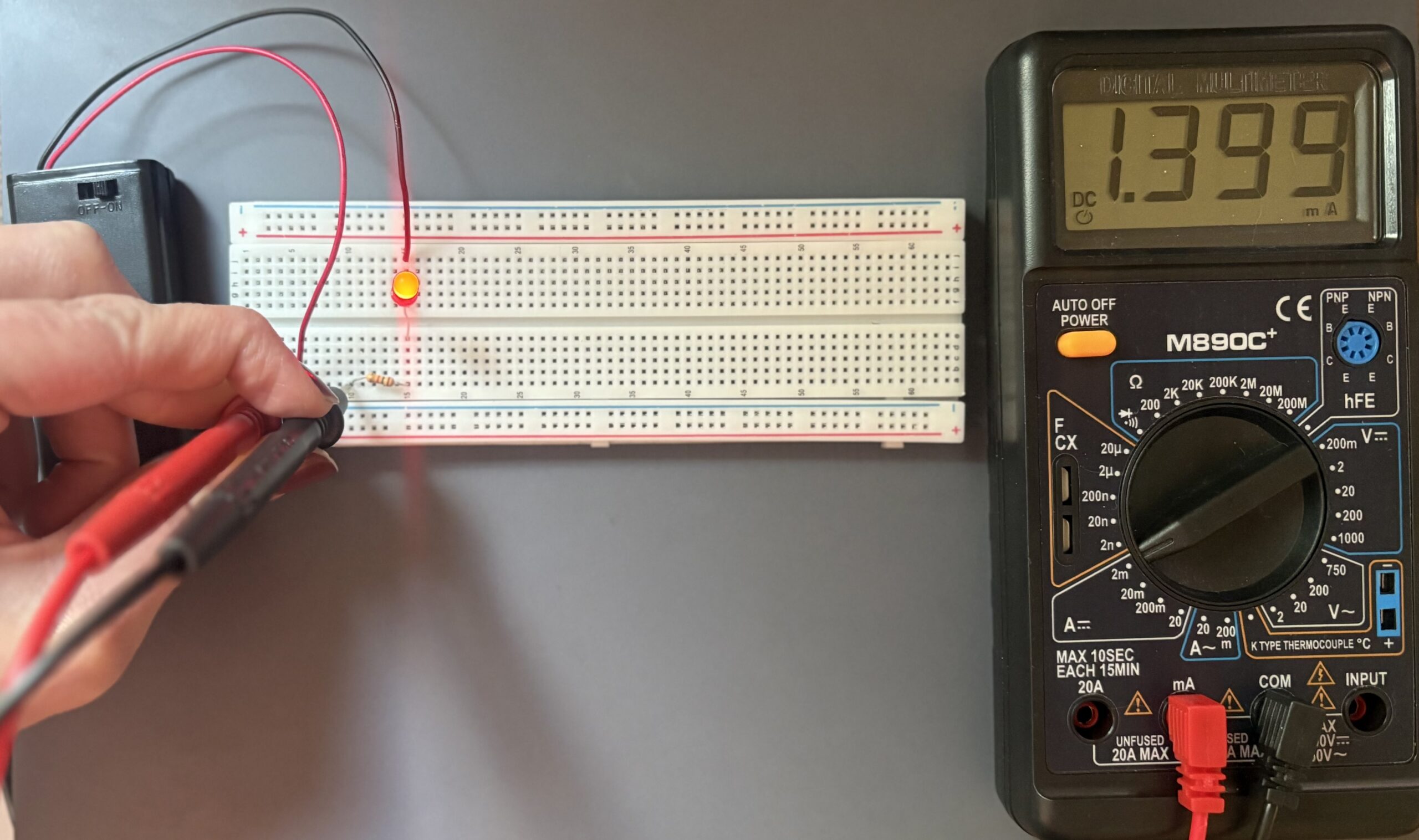
Step 3: Measure current. Break the circuit, insert the multimeter in series, measure current, and record the measurement in the Data Table. |
|
INSTRUCTOR NOTE |
|---|
|
Emphasize: the multimeter goes into the series to measure current. If learners are not using a multimeter, they could also use an ammeter, or current meter. |
|
PROCEDURE |
|---|
|
Step 4: Calculate power using P = V × I. Record the result in watts. |
|
PROCEDURE |
|---|
|
Step 5: Assume the LED runs for two hours. Calculate energy using E = P × t and record the result in watt-hours. |
Data Table: Power & Energy Calculations
|
Resistor (Ohm) |
Measured Voltage (Volt) |
Measured Current (Ampere) |
Calculated Power (Watt) |
Calculated Energy (Watt-hour) |
|---|---|---|---|---|
|
|
|
|
|
|
|
|
|
|
|
|
|
|
|
|
|
|
|
IF LEARNERS ARE STUCK, ASK |
|---|
|
|
THINK-PAIR-SHARE |
|---|
|
T: Transform the Learning
Anticipated timing: 20 minutes
Purpose: Apply measurement and calculation to an engineering modification and connect the results to real energy systems.
Engineering Application — Procedure
|
PURPOSE |
|---|
|
Learners modify one variable while keeping voltage constant, then predict, measure, calculate, and compare how the change affects power. |
|
PROCEDURE |
||||||||||||||||||||||||||||||||
|---|---|---|---|---|---|---|---|---|---|---|---|---|---|---|---|---|---|---|---|---|---|---|---|---|---|---|---|---|---|---|---|---|
Battery Resistor Table Resistor Options for a 9 V Battery
Resistor Options for a 3V Battery Pack (2 AA Batteries)
|
|
DISCUSSION QUESTIONS |
|---|
|
|
KEY TAKEAWAY |
|---|
|
Changing resistance or load changes current, and that change affects power. Engineers measure these values to make design decisions instead of relying on assumptions. |
|
TRANSITION |
|---|
|
These same measurements are exactly what we will use to evaluate our solar mini-grid system. |
Closure and Check For Understanding
Anticipated timing: 10 minutes
|
INSTRUCTOR CLOSING MESSAGE |
|---|
|
Today you used a real engineering tool to measure voltage and current, then calculated power and energy. In the mini-grid lesson, those same measurements will help us evaluate whether an energy system is reliable and useful. |
|
CHECK FOR UNDERSTANDING QUESTIONS |
|---|
|
Volted Instructor Toolkit
Differentiation Guide
Scaffold (Access) | Core (On-Level) | Extend (Challenge)
The table below maps each lesson activity to three tiers of support and challenge. Use scaffold strategies for learners with IEPs, English learners, or learners who need entry points. Use extended strategies for learners ready to go deeper. Core is the default for all learners.
|
Indicator |
Scaffold (Access) |
Core (On-Level) |
Extend (Challenge) |
|---|---|---|---|
|
Phone Charger Hook |
Offer device images and power labels to support entry points. |
Learners predict which device uses more power and explain what could be measured. |
Learners connect power ratings to energy cost or battery drain. |
|
AC/DC Concept Review |
Use the DC and AC graphs as visual anchors and define key vocabulary aloud. |
Learners distinguish direct current from alternating current. |
Learners explain why household lights do not visibly flicker at 60 Hz. |
|
Breadboard Assembly |
Provide a partially built model or peer support. |
Learners assemble a complete circuit with battery, resistor, LED, and return path. |
Learners explain each connection using breadboard row/rail language. |
|
Voltage Measurement |
Point to the two sides of the load and model probe placement. |
Learners measure voltage across the resistor or LED and record values. |
Learners compare voltage across different components. |
|
Current Measurement |
Model breaking the circuit and inserting the meter in series. |
Learners measure current safely and record values. |
Learners explain why the ammeter must be in series. |
|
Power & Energy Calculations |
Provide the formulas and a worked example. |
Learners calculate P = V × I and E = P × t for the table. |
Learners compare how a design change affects energy use over time. |
|
Engineering Modification |
Limit choices to one variable and provide sentence frames. |
Learners predict, measure, calculate, and compare one modification. |
Learners propose which design is safer, more efficient, or more useful for a mini-grid. |
|
Check for Understanding |
Allow oral explanation, labeled diagram, or word bank. |
Learners explain why engineers measure power instead of only voltage. |
Learners include evidence from their own measurements and connect to energy systems. |
Sentence Stems
|
Stem |
Used During |
|---|---|
|
I predict the current will ____ because ____. |
Engineering modification |
|
The multimeter should be placed ____ because ____. |
Voltage/current measurement |
|
Power changed because ____ changed. |
Data discussion |
|
Engineers measure power instead of only voltage because ____. |
Check for understanding |
|
This relates to a solar mini-grid because ____. |
Bridge to next lesson |
|
ASSESSMENT LOOK-FORS |
|---|
|
|
FINAL INSTRUCTOR NOTE |
|---|
|
Keep the emphasis on measurement as an engineering practice: learners are not only completing calculations, they are learning how measured evidence informs design choices. |
|
BRIDGE TO NEXT LESSON |
|---|
|
In Lesson 3, learners used a multimeter to move from observing a circuit to measuring what was happening inside it. They measured voltage and current, then used those values to calculate power and energy. In Lesson 4, learners will apply that same measurement mindset to a new source of electrical energy: the solar cell. Instead of starting with a battery, learners will investigate how light can be transformed into electrical energy through the photovoltaic effect. They will use voltage and current measurements to explore how the amount of light reaching a solar cell affects its electrical output. |